Pressure switch calibration
Main Content
- What is a pressure switch?
- Introduction
- Structure and operating principle
- Application
- Pressure switch operation procedure
A pressure switch is a type of switch activated by the pressure of a fluid. There are many different types and used for many different systems. This is a device widely used in industrial environments, with the function of regulating and controlling pressure in pipeline systems, as well as improving production operations and safety issues.
A pressure switch has many different names such as pressure relay, pressure switch, and pressure sensor,... is a simple electromechanical device, activated by pressure, switching pressure signals into switching (ON/OFF) of the electrical circuit. Pressure switches perform the task of regulating and controlling pressure in pipeline systems.
A pressure switch is a two-part device consisting of a sensor transducer and an electrical switch.
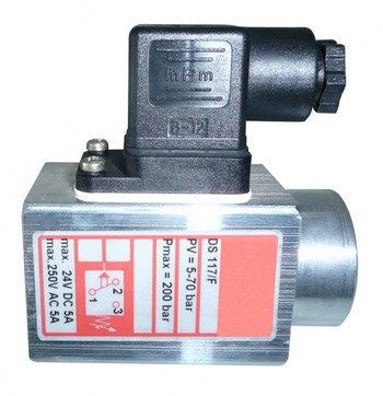
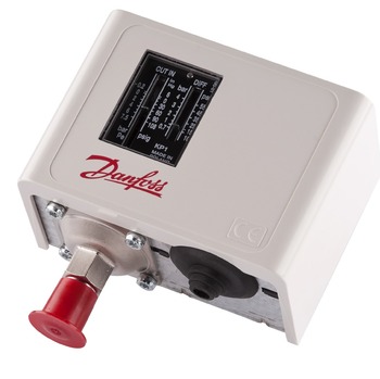

In addition, a pressure switch is also a device capable of detecting pressure changes that play the role of opening and closing an electrical switch at a predetermined level.
2. Introduction
- Mechanical pressure switches: all have traditional mechanical switches with moving parts. Based on the type of transducer, mechanical switches can be divided into two types:
- Diaphragm switch: uses a metal diaphragm to operate the switch.
- Bourdon tube switch: use a Bourdon tube to operate the switch.
Advantages: high current conversion ability and independent of voltage
- Electronic pressure switch: has no moving parts, is integrated with a pressure sensor, converts the signal at the output, and controls the valve to open and close automatically.
Advantages: longer life, better accuracy, shock, and vibration resistance.
There are two popular types on the market today: pneumatic pressure switches and hydraulic pressure switches
- Pneumatic pressure switches are divided into two types: single pressure relay and dual pressure relay
- The low-pressure relay is operated in the form of evaporating pressure and switches off the compressor circuit when the pressure drops.
- The high-pressure relay is responsible for opening and closing when the pressure of the refrigerant flow stops.
- Dual pressure relay is a combination of a low relay and a high relay, helping to cut off the pressure when it exceeds the level and lower it when it is below the allowable level.
- The hydraulic pressure switch is a relay with 3 contacts. The contact closes and the electric motor automatically shuts off when the oil, liquid, or water pressure in the system is equal to the pressure set by the operator.
3. Structure and operating principle
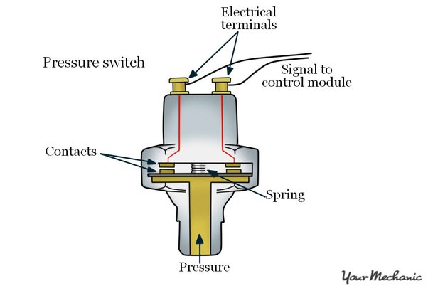
Typically, a basic pressure switch includes the following main components:

- A diaphragm Acts as a pressure-detecting element. It is usually made of flexible, pressure-sensitive material.
- A spring adjusts to adjust the setpoint or cutoff point.
- Lever used to activate or deactivate the switch
- Electrical contact allows current from an external power source to pass through them when they touch.
- Terminal equipment to connect an external power source to the contacts.
When the pressure force acting on the diaphragm is just enough to compress the spring, the pressure plate will increase.
When the impact force is large, the pressure plate will increase until the contacts are connected. At this time, the circuit will close, and power will be supplied to the circuit. Activate the electrical signal by changing the position of the contacts.
4. Application
Some of these applications include:
– Automatic pump on/off control, regulation, and pressure control inside pipelines.
– Installed in many pipelines, with high precision, control of opening and closing status, and safe operation of equipment.
– Compressor control in pneumatic applications in trucks, brake pressure in trains, cars, engine head monitoring, etc.
– Control industrial equipment such as presses, welding machines, etc.
– Triggers and alarms in ventilators and medical equipment.
– Machinery and equipment for sweeping dust in agriculture.
– Oxygen pressure monitor for medical equipment in clinics, hospitals, DNA samplers,...
5. Pressure switch calibration procedure
- The basic allowable error of the standard must not be greater than 1/4 of the smallest division value on the pressure switch's level scale.
- Create pressure greater than 120% of the set pressure value
- Sealed and increased/decreased pressure steadily; keep the pressure unchanged when reading the index
- The pressure in the system is allowed to decrease by no more than 5% of the set pressure value in 5 minutes, after being loaded for 15 minutes.
- Multimeter electric meter
- Liquid glass thermometer (0 ÷ 45) oC, division value 0,5 oC
5.2.1 Calibration conditions
- Environment temperature: (23 ± 5) oC
- Relative humidity is less than 80% RH
- The calibration room must be well-ventilated, free of dust, and not heated from one side, to avoid shocks and collisions.
5.2.1.2 Pressure Transmission Environment
- For common pressure switches, follow Table 2.
It is possible to change the pressure transmission medium from a gas to a liquid if this conversion does not cause an error greater than 1/4 of the smallest division value on the level scale of the pressure switch.
- For pressure switches using an oxygen environment:
Upper measurement limit < 0.6 MPa: air or distilled water
Upper measurement limit of 0.6 MPa or more: distilled water
- It is allowed to use gas-liquid, liquid-gas, and liquid-liquid separation chambers for calibration.
- When using a liquid pressure transmission medium, do not allow air to enter the calibration system.
- The pressure switch and reference device must be left in the calibration room for at least 2 hours.
- Clean the connector, check the pressure and calibration equipment, and push all air bubbles out of the system.
- Install the pressure switch into the pressure generating device, the allowable deviation when assembling is 5o.
- Connect the electrical wire from the pressure switch to the standard device according to the diagram specified on the standard device or multimeter.
- Set the pressure value on the level gauge according to the requirements of the place of use.
- The switch contacts must be clean, ensuring good contact, and not causing contact resistance.
- The pressure level setting part of the switch must move easily.
- The level ruler must indicate:
- Unit of measurement, pressure level limit, accuracy, pressure transmission medium, installation symbol (horizontal or vertical)...
- The division value follows the sequence: 1.10n 2.10n 5.10n (n is a positive, negative, or zero integer)
- Pressure switch:
- On the switch must be recorded the production number, usage status (normally closed or normally open), and the allowable open or closed differential pressure range.
The unit of measurement is Pascal (Pa), a multiple of Pa or other pressure measurement units recorded on the switch by the manufacturer.
The error is specified by the manufacturer. In case the manufacturer does not specify the error, the error of the pressure switch can be estimated as follows:
Error = 1/2 Smallest division value of the level ruler.
- Increase the pressure beyond the set pressure value of the switch so that the pressure switch opens and reduces the pressure below the set pressure value of the switch to close. This cycle is performed at least 5 times.
- If the pressure switch opens and closes normally through the set pressure value, the opening or closing differential pressure is within the allowable range, then continue with the next steps.
- If the opening differential pressure or closing differential pressure exceeds the allowable range, re-adjust it.
- If the pressure switch does not open and close normally over the set pressure value or cannot adjust the opening or closing differential pressure within the allowable range, this pressure switch is discarded.
- Check the continuity of the switch with a multimeter. Contacts must ensure good contact.
- Increased incoming pressure 0,9 Pset, then increase the pressure slowly at a rate of approx Pset / 01 minute until the switch opens. Record the switch opening pressure value in the calibration record.
- Continue to increase pressure at the above rate up to pressure 1,1 Pset and stop, subjecting the switch to this pressure 01 minute
- Reduce pressure slowly at the above speed until the pressure switch closes. Record the switch closing pressure value in the calibration record.
- Repeat this cycle at least 5 times.
- Calculate type B measurement uncertainty
- Calculate the combined measurement uncertainty
- Calculate the expanded measurement uncertainty
- Calculate the expanded measurement uncertainty of the switch closing pressure.
5.5 General handling
Recommended calibration cycle: 01 year
To consult and request a quote on our pressure switch calibration services, please kindly contact us via the following information:
LABORATORY: DONG TAM MEASUREMENT AND TECHNICAL TRADING SERVICE CO., LTD
ADDRESS: No.57-59 Street 11, Binh Hung Residential Area, Binh Hung Commune, Binh Chanh District, Ho Chi Minh City
TEL: 028 375 83 869 - Hotline: 0909 347 891 (Mr. Lâm)
Email: info@dongtam-mes.vn
Relative post | Xem tất cả
- Stopwatches calibration
- ORP meter calibration
- Hydrometer calibration
- Analytical and Technical balance calibration
- Analytical and Technical balance verification
- Spring dial scales verification
- Spring dial scales calibration
- Bench weight scale verification
- Bench weight scales calibration
- Platform scales verification
- Platform scales calibration
- Chlorine meter calibration




 Legal
Legal  Call: 0283.7583869
  Search for Certificate
  Contact